Dec23a.jpg

850 Fiat 850 Race Car Restoration Diary

Introduction

Hi all,

making a start on diarising activities on my second Fiat 850 series 2. I've had this one for more than 10 years, but other activities have taken precedence. The intention is to fully strip, repair and build to a race car specification. A number of other restorations documented on the web have provided inspiration for what I want to achieve - more along the lines of Fiat Abarth 1000 OTR.

Inspiration:
Inspiration1.jpg

Current State:
Exterior:
Dec23a.jpg

Dec23b.jpg

Usual rust spots:
Dec23d.jpg

Dec23c.jpg

Interior
Dec23e.jpg

Next work planned is to construct new seat mounts for the driver, to enable installation of an OMP race seat, which is considerably lower and more supportive than the original ones - major benefit that the top of my helmet does not hit the roof when driving!

Happy grinding to all this Christmas season.
The Gerard Gotch video can be found on Vimeo number 66706255. This is not the crash video I saw on TV years ago when a coupe left the track and was airborne through the trees for some distance. I could not post the link to the Vimeo video because of the 5 post rule. Should be right now!
 
Probably more than 20 years ago I tried to join HSRCA and have my Fiat rebuilt as a replica period race car. They flatly refused saying that Fiat 850 coupe's did not race in Australia! Several did of course,*

I can't recall hearing about Gotch's crash, but if I recall, I rolled an 850 at Calder the same year.

Your comment about the 850's competition history got me thinking, was it extensive at state and national level in Australia? Found the following on the Internet today.

1965 Armstrong 500 Bathurst
DNF Trevor Meehan / Pat Holmes Fiat 850
33 Ray Heffernan / Bill Daly Fiat 850
46 Bill Burns / Brian Lawler Fiat 850

1966 Gallaher 500 Bathurst
28 Trevor Meehan / Ian hindmarsh Fiat 850
Bill Burns / Alex Lazich Fiat 850

1967 Gallaher 500 Bathurst
38 Lyn Brown / David Bye Fiat 850 Coupe

1967 Southern cross rally Fiat 850 coupe

1972 Hardie Ferodo Bathurst
Gary Leggatt Fiat 850 Coupe

1972 Warwick farm oct 21
Gary Leggatt Fiat 850 coupe
 
Last edited:
[ame]http://vimeo.com/66706255[/ame]
In the Gotch incident above apparently the Rover SDI hit him on the offside fender.

Can I ask what caused your roll over? I am asking because I have not decided yet on what to do with my rear suspension. The basic plan is to cut 1 and 1/2 coils off and instal a strap to stop rear wheel tuck. It's a very long time since I drove this Fiat and after driving a MX5 with track suspension I may have been spoilt.
 
Can I ask what caused your roll over? I am asking because I have not decided yet on what to do with my rear suspension. The basic plan is to cut 1 and 1/2 coils off and instal a strap to stop rear wheel tuck. It's a very long time since I drove this Fiat and after driving a MX5 with track suspension I may have been spoilt.

Stupidity / testosterone / red mist.

I'd competed in a non track event a few weeks prior, and lifted the suspension back to standard height. Coming in to a very off camber corner, braked hard trying to make ground on the car in front and probably trail braked into the corner. Subsequently fishtailed, resulting in a perfect execution of the classic 850 wheel tuck and roll - but unfortunately no points on offer for artistic merit on the racetrack.

I've previously had the rear springs reset rather than have coils cut off, but that car was a daily driver as well as weekend warrior, and I was reluctant to make the ride too uncomfortable. Cutting the coils will change the spring rate, I've no experience to relate about that.

Camber limiting straps are probably the easiest to implement, but will be looking into short shock absorbers as an alternative to limit wheel droop. Spectators commented that the 850 often lifted the inside front wheel when cornering, which might demonstrate that front shocks cope with full extension periodically.

The other solutions like camber compensators and z bars may be possibilities. I can't quite get my head around why camber compensators work effectively, and whether tuning the suspension would be harder with this extra variable.
 
Last edited:
Arrrggggghh - too much work, not enough time for play. Thats the story of late.

Managed to squeeze a couple of hours in recently, and made up a reinforcement for the clutch pivot in the central tunnel.

Before shot- pivot assembly for clutch can be seen, cantilevered off the side of the tunnel wall. This flexes considerably in its standard form.
P1040295.jpg


Removed the pivot and found some scrap tube and threaded internal hex bar (8x1.25). This threaded bar is the right thread to screw directly onto the existing pivot rod which is attached to the tunnel wall.
P1040296.jpg


Weld the tube and threaded bar, cleaned up with grinder and spun in the drill with sandpaper to make it nice.
P1040298.jpg


Remove the pivot, and replace with washers and spacers to the equivalent width of the pivot and its plastic bushing. Screw on the bar which was just fabricated. Unfortunately when attempting this stage the lower heater pipe got in the way, and prevented installing the bar. I gave the heater pipe a few sharp whacks, and it dropped far enough to clear the reinforcing bar.
P1040300.jpg


Cut bar to length, and an angle to be flush with the outside of the tunnel.
P1040302.jpg


Fill in the gap with a washer or similar steel disc.
P1040303.jpg


Weld it in and grind it smooth
P1040305.jpg


Next instalment - replace the pin from the other side and finish the job.
 
Hi all,

the good weather has sparked a renewed interest in car related activities. Focus over the past few weeks has been a change to the routing of the heater pipes in the footwell. Here is a picture of the standard pipes weaving their way around the clutch and brake pedals.

Mar1.jpg


While having to work on the pedals is infrequent, its a pain in the butt to work around the pipes. I assume the left hand drive cars don't have the same issue. Plus I want some flexibility in the future for a possible change to dual brake cylinders. So the pipes had move over to other side of the tunnel.

First step was to make a form for bending the 16mm steel tube. Using a piece of scrap timber cut I cut a quarter circle arc on once end, and mounted the wood on a drill press with a bolt through the centre of the arc. Using a ball rasp in the drill, it was easy enough to form the guide for the steel tube.

Mar4.jpg


Mar3.jpg


Mar5.jpg


This former was used to bend the steel tube into a 90 degree bend. One end of was flared to an ID of 16mm to fit over the existing pipes, and the other end slightly flared to assist the heater hose to stay in place.

The bends were then fitted up to check they did not impinge on the clutch rod.

Mar6.jpg


Then welded in with mig, and brazed to ensure no pinholes or gaps for hot water to escape. For all the stories about poor quality steel used for constructing Fiats' the heater pipes stood up to welding very well, considering that they would have been carrying water for many years.

Mar7.jpg


In this last picture, you can see the welding which I've had to do around the edge of the floor. Quite a few of the spot welds had failed, possibly due to corrosion which had occurred beneath the seam sealer. Both sides of the car were affected to the same degree.

Thats all for now.
 
Hi all,

a minor update this time. Have made some limited progress with removal of rust area's and painting. Other than priming the passenger area which has been the focus up to date, the next item on the to do list is the fresh air plenum. Fiat, in their wisdom sited the brake fluid reservoir here as well. On my car the leaking fluid has done a good job of promoting corrosion..

JulA.jpg


After cutting out the corroded section, made up a patch using hammerform technology!
JulB.jpg


JulC.jpg


Finished patch
JulD.jpg


And welded in..
JulE.jpg


Stripped the paint in sections where I felt confident of getting good coverage of paint.Thinking of hand painting POR15 where the spray gun can't reach.
Scotchbrite has to be one of sciences more significant gifts to DIY - cleaned up the steel prior to painting.
JulG.jpg


JulH.jpg


Hopefully faster progress over the next few months.
Cheers.
 
Last edited:
Looking good.
How did you go with the other end of the tunnel where the clutch cable enters. I found mine had the cable pulled inside the rear of the tunnel. I had to fabricate a bracket to take the end of the cable. The standard set up is only tin plate and obviously does not last forever.
 
Hi,

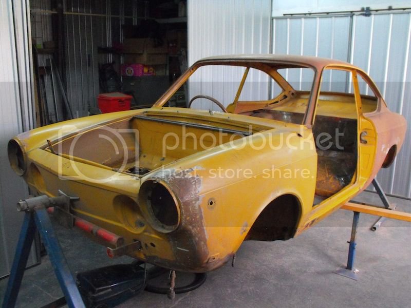
picture heavy update this time. Have been busy fabricating sections for the front trunk which has been rusted in several spots through drainage issues, normal rot in the front cross member, and the battery tray.

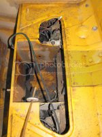
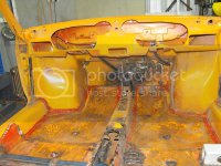
After cutting out the very corroded battery tray, and wire brushing the spare wheel well, several perforations were found, and duly attempted to make a patch to suit. After patching in some good new metal, it was evident that the acid etching had taken its toll, and much of the surrounding area was very, very thin metal.This lead to a second patch in the adjacent area to try and strengthen it.

This lead to chasing several holes with the welder when holes were blown through the paper thin metal. The end result was a patchwork of sheet metal and welding, which was very lumpy, even after running the shrinking disk over it. I’m guessing I’m not the only one to have spent hours welding, grinding, welding, grinding, welding, grinding in efforts to fill rust holes with metal.


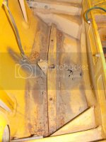
The spare wheel metal with patches shown - not happy with the result. The two blue lengths angle irons you can see sticking up are bolted on to the steering box and idler arm mounting. This is very handy, as it supports the car, allowing the front end of the rotisserie to be taken off while working in this area.


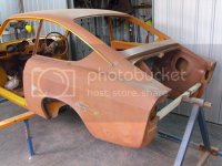
The remains of the from crossmember, at the very front of the car. Every 850 coupe i’ve had seems to suffer from the same rust.


New beginnings. This is the start of the replacement front section which houses the spare wheel, and the front cross member. Would have been nice to have a panbrake to fold up the metal sheet, but managed to get reasonable results without.


Anyone got the clamps? The front crossmember is almost a box section, but tapers in thickness in both with and depth. To make it easier to form, I made up a template with the same dimensions, and folded the metal around it.


Starting to look like the original! This version is slightly different configuration to the standard, and will enable me (hopefully) to put a 185 section spare in the front, rather than the very skinny 155 standard fare.


Getting to the harder bits - concave curves. After watching a few Youtube videos, figured out that roughing out the bowl for the wheel well with a ballpein hammer in a wooden form was the way to go. The ballpein hammer has been modified to have a slight curved face, rather than flat.


Looking less like its been beaten with a tree stump. A couple of cardboard templates help figure out whether curve is approaching the right shape.


And now its been rolled a bit with the english wheel.


…then spliced into the rest of the metal work..


..now its good enough!


It was about now, that I took a good look at the welded repairs to wheel well, and was getting less happy with my past endeavours but the minute. How are could it be to replicate the panel?


Bash the flat sheet into a nominal bowl with the trusty hammer,


then a reverse curve...


and some more hammering with a flat faced hammer.


Tidy up with the english wheel, and weld that puppy in!


Now turning attention to the very front panel. The car must have been sitting for a long time with water collecting in one corner, as there was a lot of rust perforation here. Cut off the old stuff..


And start tacking in the new section. Its right then that the mig gas runs out! Damn! Well thats it for the day.


Cheers.
 
Looking good.
How did you go with the other end of the tunnel where the clutch cable enters. I found mine had the cable pulled inside the rear of the tunnel. I had to fabricate a bracket to take the end of the cable. The standard set up is only tin plate and obviously does not last forever.

No issues that I can recall, but then again, I whipped out the manky tin and rubber thing and flung it to the darkest corner of the garage ages ago. I noted the couple of bolts in the top of the tunnel from your latest photos, and presumed you had come up with something interesting do with the clutch.
 
Hi - been ages since last post:

Finished metal work in the boot
boot1.jpg


Paint stripper and wire wheel prior to etch prime the boot area
boot2.jpg


============

The car has suffered a minor head on collision at some time in the past. The previous repair was just OK on the exterior, but the headlight seats were very buckled. Decision was to remove the headlight seats, and replace. While the seats were out, intended to massage the sheet metal and smooth out as much as practical.

To help with keeping the guard round, and un-stretched, made up a ring, the same diameter as the headlight ring. This was clamped to the guard while beating the metal.

Metal former
HL1.jpg


One of the existing headlight seats, note deformation at top.
HL2.jpg


Guard with old headlight ring excised using angle grinder.
HL3.jpg


Guard with forming ring clamped in position
HL4.jpg


HL5.jpg


Applying some heat, and beating the guard to remove creases caused by accident.
HL6.jpg


Results after beating. Some small creases still present, but exaggerated by oxide present in low spots.
HL7.jpg


HL8.jpg


Interior of guard
HL9.jpg


Used MDF (particle board) to make up former for making new headlight seats.
HL10.jpg

HL11.jpg


New seat about to be welded in.
HL12.jpg


It was about this time that I figured out that the bead in the guard was not up to scratch. Unfortunately the welded in headlight seat makes it much harder to reform the crease line.
HL13.jpg


Here you can see a former made up like a C-Clamp. The tips of the “c” has the same shape as the crease in the guard. By screwing in the bolt, pressure was applied, and after several passes (tapping it along with a hammer, managed to come up with an OK crease.
HL14.jpg

HL15.jpg


=========

Getting the nose ready for painting.
I used paint stripper to remove the old paint, which revealed quite a bit of rust scarring. This is due to all the small stone chips on the nose.
nose1.jpg


Cleaned up the nose with wire wheel on angle grinder and scourer brush. Treated with phosphoric acid to clean off remaining surface rust.
nose2.jpg


A smear of bog to cover warping and welding marks.
nose3.jpg


And some paint!!
nose4.jpg

nose5.jpg


Thats all - hopefully more soon.
 
Back
Top