There should be a TDC reference mark on the flywheel but it's not visible with the transmission attached to the engine. And it doesn't line up with any fixed mark either.
On some cars (possibly only the 124 Saloon/Sedan fitted with the OHV engines?) fitted with the old 4 speed transmission, it was visible when the crank was in the bdc position with the dust cover/shield under the flywheel removed - the 4 speed trans. bellhousing was cut away diagonally at the bottom, allowing part of the flywheel and clutch cover to be seen. The 5 speed trans. covers the entire flywheel, so the mark is not visible.
Some say this mark is a balancing mark. Some say it's just there to ensure the flywheel is refitted correctly (it'll fit on in either of 2 ways), i.e. the mark should be at the top with pistons 1 & 4 at top dead centre. This mark takes the form of a drilled dimple (it may or may not be high-lighted in white paint) located between the clutch cover and the ring gear.
As regards finding TDC is marks/pointer have been moved - various ways
1) use a tdc timing tool e,g,
https://www.classicbikeshop.co.uk/top-dead-centre-tdc-timing-tool.html
There are also versions that incorporate a graduated plunger or indeed, for better accuracy, a DTI (dial test indicator) as others have already suggested.
The problem is the plug holes on the TC engine are not vertical so... unless you want to fabricate a plug hole adaptor with an angled hole to hold the DTI or plunger vertically, such measuring devices may not work so well. (ymmv)
2) If you have a vernier or digital calipers, you should find (on the one's I've seen anyway) that as you expand the jaws to take a reading, there a tail that extends from the other end of the calipers - this is used for depth measurement of holes etc. I've used this to measure piston travel quite successfully. And it saves the cost of a DTI plus adaptor....
3) I've seen other Mechanics use a screwdriver to find TDC, worked for them.
But as s130 has pointed out, there can be inaccuracies when trying to establish TDC by measuring piston travel. One possible way to achieve better accuracy is to note the no. of degrees of crank rotation when the piston stops rising, then note the no. of degrees when the crank starts to descend and pick the midpoint as being TDC. s130 has also suggested a more accurate way would be by setting all pistons at the same height (you only have to compare no. 1 & 2 (3 & 4 will be at the same height, unless....), then turn the crank counter-clockwise by 90* (assuming you had started with no.1 piston at approx. TDC and had turned the crank clockwise to bring no.1 down to mid level in the cylinder.
My advice would be to not get too worked up about accuracy - 'near-enough will probably be good enough' (as we say over here). I remember often having to advance or retard the inlet or sometimes the exhaust cam sprocket by one, sometimes 2 teeth to get the engine to run smoothly (especially the Lancia Twin Cams) and nothing bad happened. On a standard production engine, running std. cams and std. compression ratio, you're unlikely to run into any problem. However, the golden rule is to
always turn the engine over several times gently and slowly
by hand after fitting a new belt or playing with valve timing before hitting the starter.
But, one word of caution to OP, as far as I was aware,
ALL the Fiat twin cam engines are interference engines i.e. get the valve timing wrong by more than a tooth or 2 (as mentioned above) and pistons can collide with valves and cause major damage. I'd suggest OP ask the Mechanic he consulted to disclose where he found
written info (hearsay doesn't count) that the 2 litre Fiat engine was non-interference. Or perhaps the 2 litre engine used in Fiats for the U.S. market uses such a low compression ratio compared to all other markets, that it was rendered non-interference? (I've only limited experience of the 2 litre engines).


")

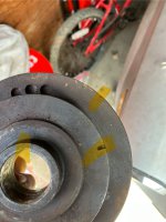
 I found the vertical mark(I think) but now I realized the pulley has two timing notches which I will be referring to as the outer and inner notch. Neither timing notch aligns with the crankshaft gear timing notch…. The inner and outer timing notches don’t even align with eachother. I tried lining up the crank gear with the vertical notch but then the pulley notches didn’t align with where they should be. There has to be something obvious I’m missing. Pictures included. The first photo- vertical notch, crank gear notch and possible alignment notch are highlighted. Second photo(reverse side of the crank pulley) - outer timing notch, inner timing notch, and crank timing notch highlighted.